
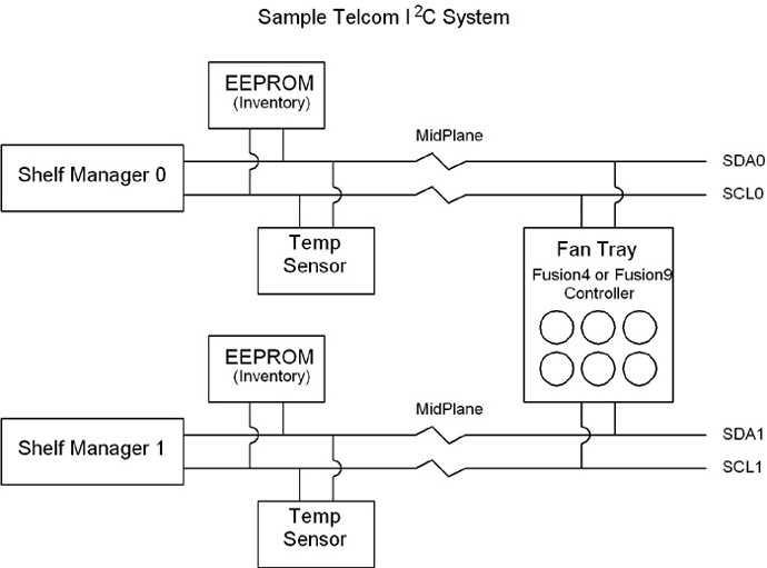
Advantages of I2C Communication for Fan Speed Control in Telecom Cooling Applications
It is generally clear why the I2C bus has been adapted as the standard format for management communications within the telecom chassis. With the wide selection of temperature sensors and EEPROM devices that can all be interconnected using only two lines, there is a strong advantage to using this interface. A logical progression is to expand this bus to interface with the fan tray to reduce connector pin count, saving cost on the interconnects, while adding flexibility to the system. This type of system can allow the shelf management to monitor thermal data from each card in the chassis and then determine what speed to run the fans at. The fan controller can report its revision and inventory information to allow decisions to be made with the same shelf manager using different variations of fan controls. In addition, nearly any number of alarm indicators can be sent with just two wires, along with data that was not available before, such as temperature readings, fan speed data, voltage output, etc.
Another large advantage of I2C is that the protocol is defined and is generally already used to interface with the shelf manager’s EEPROM and local temperature sensor. While a two-wire interface can provide many advantages described above, it is helpful to understand the origins of this chipset to avoid decisions that can cause system problems throughout product life. Fortunately, many of these problems can be eliminated with virtually no added cost by understanding how to implement the I2C bus correctly for off-board communications. This brief article provides an overview of the historical development of the two-wire bus, how this initial intent brings certain limitations, and how to overcome the inherent limitations of the two-wire open collector format. This article does expect some knowledge of the I2C protocol and does not attempt to instruct on the general use of the protocol. For a description of the I2C protocol, I refer readers to “The I2C-bus and how to use it” from Philips Semiconductor.
What is I2C anyway?
I2C or IIC stands for Inter-Integrated Circuit Bus. The original design intent was for use in audio equipment where a microcontroller-based system is needed to control volume/balance controls, a tuner circuit, an LCD panel, and EEPROM at a minimum, and often several other devices as well. The I/O requirements to interface each device in a small circuit board that fits into an automotive head unit became an impossible task given space and cost constraints.
In response, Philips created the I2C protocol, allowing all these devices to be attached to a single two-wire bus, each having a unique address. To simplify the drive requirements and allow bi-directional communication, these two lines were low current open collectors. When this bus is contained on a very small circuit board with a single ground, this design of I/O works properly.
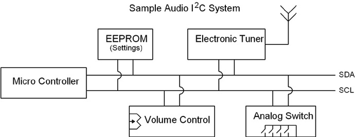
Because the interface was so successful in audio products, several IC’s were produced supporting this interface. This wide selection of chips – from memory to sensors, to A/D and D/A converters – fueled the use of I2C in numerous other applications including telecom chassis management.
I2C Adapted to Telecom Use
Without going over every variation and detail of the I2C specification, there are a few key points that will help ensure a stable and error-free system. Keeping in mind that a telecom chassis is not the same environment as a local temperature sensor and recognizing that a more error-resistant methodology is required, are the most important steps to reliable system design. Three of the most common issues are proper care for the open collector drive, correct observance of clock stretching requirements, and sufficient error detection and handling in the master driver.
Open Collector Considerations
The clock (SCL) and data (SDA) lines are both open collectors with 3mA minimum sink capability and both are bi-directional. Only 3mA of sink capability is required to be compliant, so the pull-ups must be kept weak. The maximum bus capacitance is specified at 400pf and this must be observed. If ignored, random errors can occur and capacitive filtering cannot be added. These requirements limit what is possible to enhance noise immunity. Long lines to the fan control board will add capacitance and must be taken into account when calculating the total bus capacitance. If you find that the bus capacitance is greater than 400pf, then the I2C bus routing must be modified to reduce it. Many devices may work sporadically with greater than 400pf capacitance, but proper operation cannot be guaranteed. Another important consideration is the unshielded harness in the fan tray itself. Often to simplify wiring, the communications and power are bundled in a single wrap. While this practice can work in some cases, splitting the power and I2C signals will always yield better performance. Ideally, the power is brought in on a separate connector. If this is not possible, separating the signals and power will greatly improve the noise margin. Another method to reduce noise is to terminate both ends of the transmission line with pull-up resistors. The total source current of the bus must be observed when several cards have their own pull-ups. The total source current cannot exceed 3mA to be compliant with the protocol. This specification can be ignored in a specific case; if you know the sink current of all the devices on the bus and they all have greater limits than the 3mA minimum specified, a lower pull-up resistor can be used to improve noise performance.
Clock Stretching
The clock (SCL) is also bidirectional. Most synchronous communications are clocked by the master. I2C defines that the master initiates the clock signals; however, the master must observe when the clock is held externally low and wait for the clock to be released. This allows multi-master bus devices to handle arbitration and allows the slave to delay transmission until data is ready. When communicating with a dedicated memory or sensor chip, this part of the protocol can often be ignored with no notable effects. This is because these parts use dedicated hardware to load the registers and the time delay is less than the clock cycle so clock stretching is not required. With a fan controller or any general microcontroller device, there can be a delay while firmware determines what data is loaded into the data buffer. I2C allows for this delay by allowing the slave to hold the clock low while retrieving the data. If the master simply toggles the clock without monitoring its level, it may sample data when the clock is still low and the data will give an erroneous high data. Additionally, the master will think it produced more clock pulses than were generated on the bus which will cause the slave to be out of synchronization with the master, causing further errors. When this happens on a read there is no way for the slave to inform the master of the error, so the master can continue reading invalid data indefinitely.
Error Detection
Another common cause of problems is the misconception that I2C is a complete protocol. I2C is a hardware definition; it is not a software protocol. Once a device receives a read address from the master it will respond with an acknowledge. This indicates to the master that a device is connected with this address and it is ready. From this point on in the communication string, the master generates the acknowledge signal to tell the slave when to end the transmission. The slave has no way to indicate an error to the master during this entire transmission. A transmission that is prone to noise glitches cannot be implemented with a “read and go on” approach and ensure consistent results. With a short bus contained in a quiet circuit, this approach can often work. With long unshielded cables bundled with high power lines, this approach is nearly certain to fail. The question is when and how often. Fortunately, this problem can be easily overcome by using single-byte access commands and oversampling, which can be handled in the master’s firmware/software and does not generally add cost to the system hardware.
Conclusion
These three guidelines will not correct every issue that is possible to encounter in an I2C system, although they will avoid most of the common pitfalls of implementing an I2C interface in a telecom fan tray. About the author: Nathan Lavoie has a BSEE from the University of Vermont and is the Vice President of Engineering of Control Resources Inc., where he has developed more than 50 I2C-based custom fan controllers.
Additional I2C reference information:
• Click on I2C Flowchart for a sample I2C protocol flow diagram.
• Download I2C Article in PDF format.